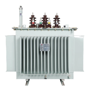
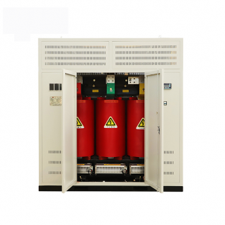
The windings and core are crucial components for transmitting and transforming electromagnetic energy in a transformer. Accurate assessment, detection, and rectification of core faults are essential to ensure the normal operation of a transformer.
I. Hazards, Causes, and Types of Multi-point Grounding Faults in Transformer Cores
Hazards of Multiple Grounding Faults in Transformer Cores:Multiple grounding faults in the transformer core should not occur during normal operation. When a transformer operates normally, an alternating magnetic field exists around the windings. Due to electromagnetic induction, parasitic capacitance exists between the high-voltage winding and the low-voltage winding, between the low-voltage winding and the core, and between the core and the outer shell. The energized winding will generate a floating potential in the core with respect to the ground due to the coupling effect of the parasitic capacitance. Since the distances between the core and other metal components with the windings are unequal, there exists a potential difference between these components. When the potential difference between two points reaches the insulation breakdown level, spark discharges occur. This type of discharge is intermittent and, over time, adversely affects both the transformer oil and solid insulation.To eliminate this phenomenon, the core should be reliably connected to the outer shell to bring it to the same potential. However, when there are two or more grounding points on the core or other metal components, the grounding points form a closed loop, causing circulating currents, localized overheating, oil decomposition, and a decrease in insulation performance. In severe cases, it can lead to a major accident, such as burning the core silicon steel sheets. Therefore, only a single grounding point is allowed for the core of the main transformer.
Causes of Core Grounding Faults:The main causes of grounding faults in transformer cores are as follows: short circuits caused by poor construction techniques and design of grounding strips; multiple grounding points caused by accessories and external factors; grounding faults caused by metal foreign objects left in the main transformer and rough core processes, such as burrs, rust, and welding slag.
Types of Core FaultsCommon types of faults in transformer cores include the following six: (1) Contact between the core and the shell or clamps during installation. This can occur when the stabilizing pin used for transport on the top cover of the oil tank is neglected or flipped over during removal, causing the core to contact the shell. Other instances include the core clamps touching the core column, the silicon steel sheets curling and contacting the clamp limbs, the paper between the core lower clamp foot and the iron yoke falling off, and the temperature gauge seat sleeve being too long and contacting the clamp or iron yoke or core column. (2) Short circuit caused by the excessive length of the through-core bolt steel seat sleeve and the shorting of the silicon steel sheets. (3) Presence of foreign objects in the oil tank causing local short circuits in the silicon steel sheets. Examples include a screwdriver found between the clamps and the iron yoke in a 31500/110 power transformer at a power station in Shanxi, and a 120mm-long copper wire found during the hood inspection of a 60000/220 power transformer at another substation. (4) Moisture or damage to the insulation of the core, such as sedimentation of sludge and moisture, leading to a decrease in insulation resistance. Moisture or damage to insulation in clamps, iron pads, and iron boxes (paper or wood blocks) can also result in high-resistance multiple grounding points in the core. (5) Wear of the pump shaft bearings, entry of metal powder into the oil tank, accumulation at the bottom, and formation of a bridge circuit under electromagnetic forces, causing the lower iron rail to connect with the pad or tank bottom, resulting in multiple grounding points. (6) Poor operation and maintenance, failure to conduct periodic inspections as scheduled.
II. Testing and handling methods for transformer core faults
Transformer Core Fault Testing Methods
(1) Clamp Ammeter Method (Online Measurement): For transformers with externally led cores, the clamp ammeter method is employed for accurate, non-stop testing of multiple grounding faults in the core. Regularly measure the grounding lead current every year, and the current should generally be below 100 milliamperes. If it exceeds this value, enhanced monitoring is necessary. After the transformer is put into operation, measure the grounding line resistance continuously several times as the initial value. If the initial value is already large, indicating a significant leakage flux from the transformer itself, subsequent measurements with little difference can be considered as having no faulty grounding points. If the grounding line current is greater than 1 ampere and significantly increases compared to the initial value, it may be indicative of a low-resistance grounding or a metal grounding fault, which should be addressed promptly.
(2) Chromatographic Analysis Method (Oil Sampling with Power On): Chromatographic analysis is conducted on oil samples. If the total hydrocarbons show a significant increase, with methane and ethylene dominating the gas composition, and carbon monoxide and carbon dioxide gases remaining relatively unchanged or changing only minimally compared to previous levels, this suggests bare metal overheating. It may be caused by multiple grounding faults in the core or damage to the insulation between the core and the silicon steel sheets. Further investigation is required. If acetylene appears in the total hydrocarbons, it is likely an intermittently occurring unstable type of multiple grounding faults in the core.
(3) Insulation Resistance Method (Power-off Testing): Use a 2500-volt megohmmeter to measure the resistance between the core and the shell. If the insulation resistance is 200 megaohms or higher, it indicates good insulation in the core. If the megohmmeter indicates continuity between the core and the shell, switch to an ohmmeter to measure the resistance between the core and the shell. If the measured value is between 200 and 400 ohms, it suggests high-resistance grounding points in the core, requiring treatment for multiple grounding faults in the transformer core.
If the measured value is above 1000 ohms, with a small current flowing through the ground wire and difficult to eliminate the fault, it can continue to operate without treatment. Regular online monitoring should be performed, such as using the clamp ammeter method (for transformers with externally led cores) or oil chromatographic analysis. If anomalies are detected, then further treatment is needed. If the measured value is between 1 and 2 ohms, it indicates metal grounding points in the core, and treatment of the transformer is necessary.
2. Methods for Dealing with Multiple Grounding Points in Transformer Cores:
(1) For transformers with external grounding lines on the core, a resistor can be connected in series on the core grounding circuit to limit the current flow in the core grounding. This method is only suitable for use as an emergency measure.
(2) In the case of core grounding faults caused by metal foreign objects, a general procedure is to conduct a hood inspection, which can typically reveal the problem.
(3) For grounding faults caused by core burrs or the accumulation of metal powder, methods such as capacitor discharge impact, alternating current arc, and large current impact have shown more noticeable effects.
III. Quality Standards for Transformer Core Overhauls
The core should be flat, with no peeling of insulation paint, tight laminations, and the side silicon steel sheets should not be raised or wavy. The surfaces of the core should be free of oil and impurities, and there should be no short circuits or overlaps between laminations. The gap at the joints should meet the requirements.
Good insulation should be maintained between the core and the upper and lower clamps, yoke, pressure plate, and base plate;
There should be a noticeable uniform gap between the steel pressure plate and the core; the insulation pressure plate should be intact, free of damage and cracks, and with appropriate fastening;
The steel pressure plate should not form a closed loop and should have a single grounding point;
After opening the connecting pieces between the upper clamp and the core and the connecting pieces between the steel pressure plate and the upper clamp, measure the insulation resistance between the core and the upper and lower clamps and between the steel pressure plate and the core. There should be no significant changes compared to previous tests;
The bolts should be securely fastened, and there should be no loosening of the positive and negative pressure pins and locking nuts on the clamps. They should have good contact with the insulation gaskets and no traces of discharge burns. The reverse pressure pins should have a sufficient distance from the upper clamp;
The core bolts should be securely fastened, and their insulation resistance should show no significant changes compared to previous tests;
The oil passages should be unobstructed, the oil passage pads should not be loose or blocked, and they should be arranged neatly;
The core should only have a single grounding point. The grounding piece should be a copper piece with a thickness of 0.5mm and a width of not less than 30mm, inserted into the 3-4 core levels. For large transformers, the insertion depth should be not less than 80mm, and the exposed part should be wrapped in insulation to prevent short circuits in the core;
It should be securely fastened with sufficient mechanical strength, good insulation without forming a closed loop, and no contact with the core;